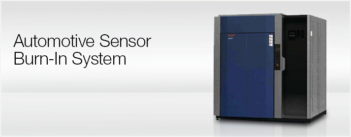
The Automotive Sensor Burn-In System provides a device for screening an automotive sensor that is mounted on an attitude control unit, etc. for automobile safety.
Sensors used for safety purposes are required to have extremely high reliability, and a screening process is required for all shipped items to ensure quality control.
The production process incorporates a burn-in process for these devices, and the initial defective products are screened to reduce the number of defective products that are shipped.
- Applicable devices and the need for burn-in inspection
-
The automotive sensor generally detects the rotation angle speed (change in angle over time) of a body. There are 2-axis and 3-axis sensors, and one example is a gyro sensor.
These sensors are commonly used in automobiles, digital mobile devices (digital cameras, cell phones, etc.), and gaming devices, and they are gaining attention as next-generation devices for improving safety and operability.
The automotive angle speed sensor, in particular, is a device required to detect safety-related attitude control, and the need for burn-in inspection is growing.

- Features
-
- Monitors the output voltage from automotive sensors for each channel to determine the quality.
- Devices are installed on a burn-in board, and up to 48 boards can be loaded into a chamber.
- Comes with an automatic insertion/extraction mechanism to enable insertion of a batch of card edge connectors for multiple burn-in boards.
- Optimal test conditions for electrifying the automotive sensor can be provided as required.
- Set the hot chamber from +70°C to +150°C.
- Use a computer to configure test settings, start and stop tests, determine quality, configure chamber control settings and more.
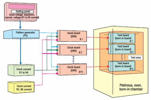
- Reference example: System block diagram

- Specifications
-
Item Specification values (reference values because of individual support products) Burn-in system Application voltage +5.5V to 7.0V Voltage application accuracy Within ±0.1 V Voltage application setting Continuously energized test, power cycling test Power cycling test Set ON/OFF in increments of 5 to 60 seconds Device output monitor Comparator voltage +0.45 to +5.0 V (fixed after fine tune setting with trimmer at initial introduction) Output monitor circuit Monitors device output up to 300 times per slot Chamber Control temperature range +70°C to +150°C Temperature uniformity ±3°C (load, maximum 600 W)*1 Temperature heat-up time 40°C ⇒ 125°C within 60 min. (no specimen, no load) Slot specifications 48 slots (maximum 14,400 loaded devices) -
*1 Conditions of the temperature control range, temperature uniformity width, and other factors may vary according to the device configuration of your environment. These specifications are listed for reference purposes.
Recommended products for customers viewing this product


