
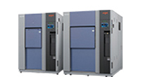
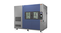
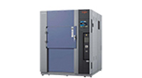
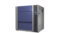
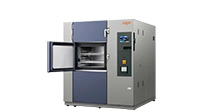
Highly Accelerated Air to Air Thermal Shock Chamber
Overview
Highly Accelerated Air Thermal Shock Testing: A test method that accelerates thermal shock testing
Chamber for HAATS (Highly Accelerated Air Thermal Shock) testing
- Features
-
- Significantly shortened testing time
This chamber achieves a temperature recovery between +125°C and -40°C only in 3 minutes by high air velocity and unique air flow control which reduce testing time approximately 1/3 compared to conventional models. - Ensures correlation with thermal shock testing
Enables more efficient evaluations by retaining test accuracy. - Defrost-free with no test interruptions
No interruptions required during testing for defrosting with a defrost-free function which prevents from frost.
Saves time and power consumption for defrosting. - Available for conventional thermal shock testing
Enables to perform conventional thermal shock testing by equipping with a air flow adjuster for allowing reduction of air velocity.
Provides a variety of thermal shock testing with a variety of evaluation conditions flexibly.
- Significantly shortened testing time
Test cases of confirming validity of velocity (one-third the exposure time of conventional test)
Please scroll horizontally to look at table below.
| Highly accelerated thermal cycle test (air chamber) |
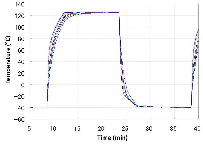
Conventional thermal cycle test (air chamber) |
|||||
|---|---|---|---|---|---|---|
| Temperature range | -40°C ⇔ +125°C(⊿t=165°C) | |||||
| Exposure time | 5 minutes | 15 minutes | ||||
| Temperature profile | 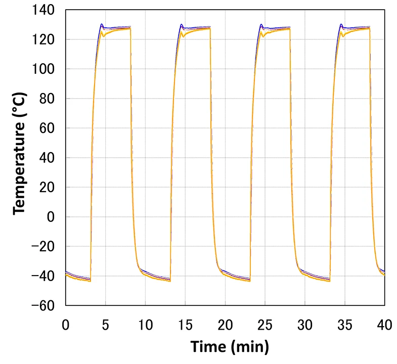 |
 |
||||
| Hot (+123°C or more) |
Cold (-38°C or less) |
Hot (+123°C or more) |
Cold (-38°C or less) |
|||
| Substrate temperature recovery time | 1.1 to 1.3 minutes | 1.5 to 2.5 minutes | Substrate temperature recovery time | 3.4 to 7.9 minutes | 3.7 to 6.2 minutes | |
| Substrate temperature hold time | 3.7 to 3.9 minutes | 3.5 to 2.5 minutes | Substrate temperature hold time | 7.1 to 11.6 minutes | 8.8 to 11.3 minutes | |
Specifications
Please scroll horizontally to look at table below.
| Model | TSH-13-W | ||
|---|---|---|---|
| Method | Temperature recovery (highly accelerated operation) |
||
| Performance | High-temperature exposure | +60°C to +200°C | |
| Low-temperature exposure | -70°C to 0°C | ||
| Temperature recovery (highly accelerated operation) |
High-temperature exposure: +125°C 5 minutes Low-temperature exposure: -40°C 5 minutes Specimen: 1.36 kg (using a glass epoxy substrate) Temperature recovery rate: within 3 minutes |
||
| System | Cascade refrigeration system | ||
| Construction | Inside capacity | 12L | |
| Test area dimensions | W300×H200×D200mm | ||
| Outside dimensions | W1430×H1900×D1370mm | ||
| Weight | Approx. 1,070 kg | ||
- Examples
-
・-40°C ⇔ +125°C Test area recovery time 5 min, exposure time 5 min Specimen: DC-DC converter for vehicle ・-40°C ⇔ +65°C Test area recovery time 5 min Specimen: Battery cell for vehicle
Recommended products
-
 Conductor Resistance Evaluation System
-
 Air to Air Thermal Shock Chambers
Fixed test area type /
Elevator type -
 Large Capacity Liquid to Liquid Thermal Shock Chamber
-
 Thermal Shock Chamber 300°C Specification
-
 Large Capacity Thermal Shock Chamber
TSA-603EL-W
(600L) -
 Air to Air Thermal Shock Chamber with Humidity
-
 High-Rate Thermal Cycle Chamber
- Contact us
- Customer Support Desk
Environmental
Test Chambers
- Temperature
(& Humidity) Chambers /
Rapid-Rate Thermal Cycle Chambers- Platinous J Series Temperature
(& Humidity) Chamber - Environmental Stress Chamber
AR series - Rapid-Rate Thermal Cycle Chamber
- Bench-Top Type Temperature
(& Humidity) Chamber - Constant Climate Cabinet
- Compact Ultra Low Temperature Chamber
- Stability Test Chamber (CSH)
- Stability Test Chamber (CWH)
- Walk-In Chamber E Series / High-power Series
- Highly Accelerated Stress Test System (HAST Chamber)
- Temperature
(& Humidity) Chamber FD Series - High-Rate Thermal Cycle Chamber
- Altitude Temperature
Chamber - Altitude Temperature
(& Humidity) Chamber
MZ Series - Large Highly Accelerated Stress Test System
(HAST Chamber)
- Platinous J Series Temperature
- Thermal Shock Chambers
- Temperature Chambers
- Industrial Ovens
Temperature Chamber
Series - Industrial Ovens
Ultra-High Temperature Chamber - Industrial Ovens
Temperature Chamber
with Explosion Vent - Industrial Ovens Temperature Chamber with Rotating Specimen Rack
- Industrial Ovens Anaerobic Temerature Chamber
- Industrial Ovens High Performance Clean Oven
- Industrial Ovens Large Volume Temperature Chamber
- Desk-top Type High-Temp. Chambers
- Convection Oven
- Vacuum Oven
- One-Pass Oven
- Anaerobic Oven
(Less than 100ppm) - Large Clean Oven
- Slide Tray Oven
- Anaerobic Clean Oven
(SCO Series)
- Industrial Ovens
- Network Products
- Example Custom Orders