Air to Air Thermal Shock Test
- Test summary/features
-
Air to air thermal shock tests evaluates the reliability of test samples by repeatedly applying rapidly alternating high and low temperatures to them.
The expansion and contraction caused by the temperature variation generate stress from differences in the expansion rates of parts made of different bonded materials. Stress is also generated by differences in the heat capacity and thermal time constant of each component element of devices. Applying these stresses repeatedly leads to cracks and rupturing.
The repeated action of stress causes accumulation of material fatigue, sometimes leading to rupturing at a lower strength than the static strength. Repeated stress can also cause bonded parts to crack, coatings to peel, and screws to loosen.
- Thermal shock tests; application examples; simulation testing of solder cracking, solder rupturing and other market failures
-
- Evaluating PCB mounting reliability after a change in lead-free solder or another connection material
- Evaluating reliability after a change in mounting format such as BGA or CSP
- Evaluating connection resistance by connector temperature variation
- Checking for cracks by thermal deformation of molded plastic parts
- Checking for cracking, peeling or seal leaks in bonded materials
- Evaluating combinations of different material types such as plastic with inserted nuts
-
Screening processes before product shipment
Examples of thermal shock tests used to evaluate solder connections
- Test equipment
-
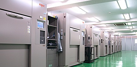
The test equipment consists of the three chambers shown below. Thermal shock is applied automatically and continuously by switching the air flow entering the test area with dampers. Either of two types of thermal shock can be selected according to how the dampers are switched: Two-zone testing (low temperature to high temperature), or three-zone testing (low temperature to ambient temperature to high temperature).
Since the test area is always fixed in place and the temperature of the entering air flow is switched, power or measurement wiring can easily be supplied to the test sample.
Wiring is supplied through a cable port on the left surface of the test area.
- High-temperature (300°C) thermal shock test equipment available
-
Power semiconductors needed in power conversion circuits (for applications such as hybrid vehicle motor control or household appliance power control) need to be heat resistant to withstand the high-temperature stress created by high-capacity electric current. These power semiconductors therefore require thermal shock testing under test conditions that expose them to high temperatures of over 200°C.
To meet this demand, ESPEC has thermal shock test equipment enabling high-temperature exposure settings of up to 300°C.
- Equipment particulars
-
- Thermal Shock Chamber (installed at ESPEC test facilities)

| TSA Series Thermal Shock Chamber | ||||||
| Temperature ranges | High-temperature exposure | +60 to +200(250)°C | +600 to 0 to +300°C | |||
| Low-temperature exposure | -70 to 0°C | -65 to 0°C | -700 to 0°C | |||
| Test area dimensions (W×H×D) | 410×460× 370mm |
650×460× 370mm |
650×460× 670mm |
970×460× 670mm |
650×460× 670mm |
|
* ESPEC also has various other test equipment models to meet demand for various temperature variation capacities and test area sizes (capacities).
