Insulation Resistance Evaluation
- Test summary/features
-
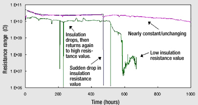
When a voltage is applied to a PCB or similar component under a condition of high humidity, a phenomenon called Electro-chemical migration occurs in which metal ions move from one metal electrode to the other, causing precipitation of metal or compounds. Short-circuiting between electrodes can result as the dissolution and precipitation progress.
The following have been reported as factors that influence the rate of Electro-chemical migration:- Type of metal electrodes
- Applied voltage
- Insulation material type, structure, configuration, etc.
- Environmental conditions: Temperature, humidity, gas, etc.
- Other: Chemical residue left after PCB manufacture, impurities on insulation material, etc.
As PCB mounting densities have increased to meet demand for smaller and lighter electronic devices, there has been a rapid shift toward narrower-pitch electronic parts, finer-patterned PCBs, and integration of PCBs with other parts. The result has been smaller gaps between conductors, shorter insulation distances and higher average electric field strengths, as well as greater effects from local fields. And since the rise of mobile electronic devices has resulted in more diverse operating conditions, evaluating insulation reliability has become crucial.
- Test equipment
-
ESPEC's Electro-chemical Migration Evaluation Systems (AMI Series) make Electro-chemical migration-based life evaluation and insulation resistance evaluation efficient and simple, and support numerous applications ranging from low-voltage testing to high-voltage testing.
-
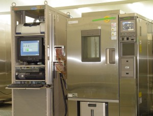
- Electro-chemical Migration Evaluation System (installed at Kobe, Utsunomiya and Toyota Test Centers)
-
- Features
-
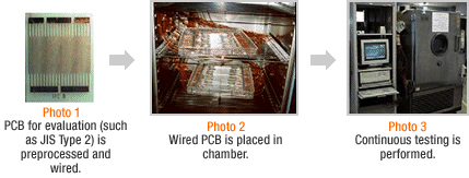
Standard methods of Electro-chemical migration evaluation testing consist of placing the PCB in a high-temperature/humidity environment and applying DC voltage to it. The test sample is then extracted at constant time intervals from the temperature chamber, and insulation resistance is measured manually.
But when samples are measured outside the temperature chamber, many factors lead to variation in measurement results. For example, measurement results are greatly affected by the preservation state and processing conditions after sample extraction, and care must be taken with the measurement method.
In contrast, measurement done continuously with an automatic insulation resistance evaluation system enables direct measurement with the PCB for evaluation still in the temperature and humidity chamber, allowing evaluation under constant environmental conditions. As a result, these systems can measure the change in insulation deterioration over time in a manner more closely meeting the test objective than conventional test methods can.
- Main specifications
-
Stress application voltage ranges: 1 to 100 VDC, 1 to 500 VDC
Number of channels: 50 to 150
-
- 2.5 kV High-voltage Electro-chemical Migration Evaluation System (installed at Utsunomiya Test Center)
-
Power semiconductors are needed in the power conversion circuits used in applications such as high-efficiency use of electrical energy, hybrid vehicle motor control, and household appliance power control.
Since the circuit boards used to control these power semiconductors need to be resistant to Electro-chemical migration at high voltages, there is a need to evaluate their Electro-chemical migration resistance characteristic.
Another issue is PID (potential induced degradation), a type of deterioration that reduces output when leak current is generated due to a large potential difference between a solar battery frame and module circuit. High-voltage Electro-chemical Migration Evaluation Systems can also evaluate PID.
- Features
-
Slow voltage application control function
When increasing the stress voltage, a 2-second wait is inserted every 100 V to create a stepped increase. When decreasing the voltage, it is decreased immediately.
Stress power supply positive-side relay
Stops the voltage applied to the sample when not performing a test or when ending the test for an individual channel.
Stress voltage monitor
Displays the monitored voltage value of individual stress power supply units.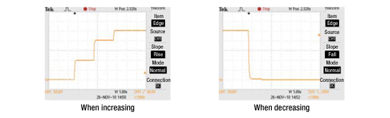
- Main specifications
-
Stress application voltage range: 30 to 2,500 VDC
Number of channels: 50* Simple migration evaluation equipment supporting a stress application voltage of 1,000 V and 20 channels is available at each test facility (inquire for more information).