Capacitor Leakage Test System
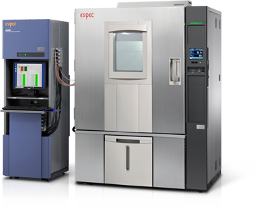
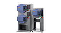
Electronic parts that support compact, high-performance electronic devices. As the structure of electronic parts continues to become more dense and complicated, it is also decreasing in size, and there is active development of parts that are compact, high capacity, environmentally friendly and with lower ESR. Among these, condensers are essential key devices for the innovation of laptops, cell phones, mobile devices, and Bluetooth and other multimedia devices. Reliability testing to ensure the performance and safety of these will be even more important in the future. ESPEC has developed the Capacitor Leakage Test System that enables automatic evaluation of insulation degradation characteristics of condensers in high temperature and high temperature/humidity test environments. This system applies voltage to the condenser in the desired high temperature (humidity) test environment and obtains the leak current caused by insulation breakdown.
This automatic measurement system comes with various data processing and analysis functions, including display of leak current caused by insulation breakdown, failure detection and calculation, and failure analysis using cumulative hazards.
Overview of Equipment
- Features
-
- Automatic evaluation of insulation degradation characteristics of condensers in high temperature and high temperature/humidity environments.
- Can be expanded to a maximum of 300 channels.
- Measurement can be performed with an insulation resistance range of 2.0×10E+05 to 1.0×10E+13. (when applying 100 V)
- Set test conditions in units of 25 channels.
- Display and check the temperature and humidity of the temperature chamber, number of failure occurrences, and section failure rate in real-time.
- Evaluate the insulation degradation characteristics from the histogram of the number of failure occurrences, the failure rate curve, and data analysis using the cumulative hazards.
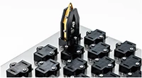
- Supports various condenser mounting jigs, including board mounting and contact probe types.
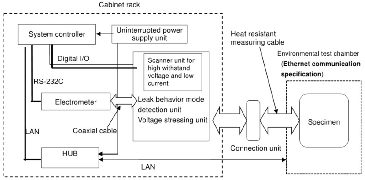
- Construction
-
- Insulation degradation testing of ceramic chip condensers and other condensers
Detailed Specifications
Please scroll horizontally to look at table below.
| Type | Stress constant voltage 100 V specification | Stress constant voltage 300 V specification (OPTION) |
Stress constant voltage 500 V specification (OPTION) |
||
|---|---|---|---|---|---|
| Channel configuration | 25 to 300 ch/rack | ||||
| Channel control | 5 ch/25 ch | ||||
| Software*1 | Windows OS | ||||
| Stress power supply | Stress voltage | 0 V DC, 1.0 to 100 V DC | 0 V DC, 1.0 to 300 V DC | 0 V DC, 1.0 to 500 V DC | |
| Min. set voltage resolution | 0.1 V (1.0 to 100 V. Can be set independently of the measurement voltage.) |
0.1 V (when set at 1 to 200 V) 1.0 V (when set at 200 to 300 V) |
0.1 V (when set at 1 to 200 V) 1.0 V (when set at 200 to 500 V) |
||
| Applied voltage accuracy | ±(0.7% of set voltage + 300 mV) | ||||
| Measurement functions | Resistance measurement range (Ω) | 2.0×10⁵ to 1.0×10¹³ (when applying 100 V) 2.0×10³ to 1.0×10¹¹ (when applying 1 V) |
6.0×10⁵ to 3.0×10¹³ (when applying 300 V) 2.0×10³ to 1.0×10¹¹ (when applying 1 V) |
1.0×10⁶ to 5.0×10¹³ (when applying 500 V) 2.0×10³ to 1.0×10¹¹ (when applying 1 V) |
|
| Measurement accuracy | 10 TΩ±30% (when applying 100 V) | ||||
| Measurement voltage | 1.0 to 100 V DC (0.1 increments) | 1.0 to 300 V DC (1.0 to 200 V: 0.1 increments) (200 to 300 V: 1.0 increments) |
1.0 to 500 V DC (1.0 to 200 V: 0.1 increments) (200 to 500 V: 1.0 increments) |
||
| Leakage current detection speed | Constantly detects with speed of less than 100 μs. | ||||
| Measurement cable | Type | + side | Heat-resistant single cable | ||
| - side | Coaxial cable (one-layer shield) | ||||
| Coating material | Teflon (heat resistance +150°C) | ||||
| Length | Between scanner unit and connection unit: 2.5 m Between connection unit and end: 1.5 m |
||||
| Connection unit | 25 ch/unit + side: Metal connectors, - side: Square coaxial connectors |
||||
| No. of measurement instruments | 25 ch to 150 ch: 1 175 ch to 300 ch: 2 |
||||
| Accessories | Communication cable (Ethernet), setup CD, operation manual (1 set), maintenance (10 MΩ) resistor box, warranty certificate | ||||
| Outside dimensions*2 | W530 x H1750 x D1040 mm | ||||
| Power supply | 100 V AC, 1 φ, 15 A | ||||
- *1 The (software) operating environment may change as a result of version changes in the Windows OS. Please check the current OS version.
- *2 Excludes protrusions.
Recommended products for customers viewing this product
- Contact us
- Customer Support Desk
Measurement & Evaluation Systems / Semiconductor-related Equipment
-
Measurement & Evaluation Systems
- Electro-chemical Migration Evaluation System(Leakage Current Evaluation System)
- High Voltage Bias Insulation Resistance Evaluation System
- Capacitor Leakage Test System
- High Temperature Reverse Bias Test System
- TDDB (Time-Dependent Dielectric Breakdown) Evaluation System
- Conductor Resistance Evaluation System
- Electromigration Evaluation System
- PV Thermal-Bias Combo Test System
- Semiconductor Parametric Test System
- Capacitor / Inductor Temperature Characteristic Evaluation System
- PV I-V Evaluation System (PV Thermal-Light Combo Test System)
- Power Cycle Test System
- Semiconductor-related Equipment