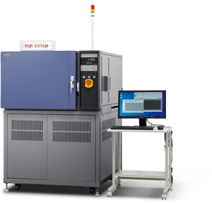
High Voltage Bias Insulation Resistance Evaluation System
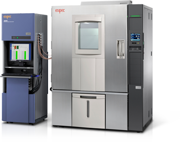
Overview of Equipment
The High Voltage Bias Insulation Resistance Evaluation System is a measurement system used to evaluate the insulation of insulation material and the reliability of the electro-chemical migration phenomenon that results in insulation-failure due to moisture absorption, etc., associated with an increase in the system voltage in connection with electronic parts and energy efficiency.
The demand for power devices is increasing as automobiles become more electronic based and the market demand for energy-efficient home appliances increases.
In terms of more electronic-based automobiles, power devices (IGBT) for electric and hybrid vehicles continue to be developed, ECU power devices continue to evolve, and miniaturization technology used to store more ECUs in a tight body space continues to grow.
Meanwhile, we are seeing greater energy efficiency (using GaN, SiC, etc.) in power devices used in air conditioners, refrigerators, LCD TVs, and other home appliances.
The need for reliability evaluation of mounting substrates with high heat radiation properties and insulation material used in power devices is being reconsidered, and the importance of the continuous measurement of insulation resistance using this system is gaining attention.
This system enables measurement under high-voltage of 2500 V with high accuracy. In addition, it is equipped with a stress voltage control function that enables a slow voltage application to control overshooting at a high voltage and a leak touch function that detects momentary leak current.
A protective electronic circuit unit minimizes errors in voltage application and provides greater safety when a short circuit occurs.
- Features
-
- Continuously energized scanner relay system and a measuring instrument that supports international standards to ensure high-accuracy measurement.
- Constant stress voltage (stress voltage, measurement voltage) can be set in a wide range from 50 V to 2500 V.
- Equipped with stress voltage control function.
To protect the sample and ensure safety, a 1-second wait is added every 100 V when the stress voltage is increased, thereby providing a gradual increase. - Equipped with a high-speed leak detection function using a leak touch detection function.
- Edit and view real-time data with the "E-Graph" special statistical processing software.
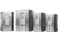
- Linked with an environmental test chamber for enhanced operability and safety.
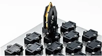
- Evaluation test case
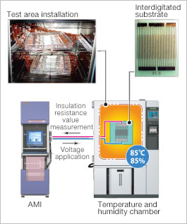
- Applicable devices
- 1. Power device mounting PCB
- Substrate material
- Heat dissipation substrate (ceramic substrate, aluminum substrate, etc.)
- Resist material
- Solder material
- Sealing material
- Semiconductor sealing material
- Mold resin material
- Substrate material
- 2. Power device supporting material
With the increase of hybrid vehicles and electric vehicles, automobiles are using more electronics and are equipped with over 100 ECUs. Because hybrid and electric vehicles are exposed to rigorous environments with high temperatures for long periods, the sealing material and substrate material must be able to withstand these environments and protect such devices. In addition, these vehicles use power devices with a large current of several hundred amperes, so there is a growing demand for material with high insulation performance, never-before-seen long-term heat resistance performance to withstand high temperatures, and heat dissipation performance.
Specifications
Please scroll horizontally to look at table below.
| High-voltage (2500 V) specifications | |
|---|---|
| Channel configuration | 25 to 150 ch per rack |
| Channel control | 5 ch / 25 ch |
| Measurement voltage | 50 to 1000 VDC / 50 to 2500 VDC * For voltages higher than 2500 V, please consult with us. (50 to 200 V: 0.1 V increments, 200 to 2500 V: 1 V increments) |
| Resistance measurement range | 1 × 10⁵ to 1 ×10¹³ Ω or higher (when applying 100 V) 1 ×10⁶ to 1 ×10¹⁴ Ω or higher (when applying 1000 V) 2.5 ×10⁶ to 2.5 ×10¹⁴ Ω or higher (when applying 2500 V) |
| Resistance measurement accuracy | Measured resistance accuracy when 1000V is applied to a 10 TΩ resistor: ±4% *1 (Measurements from 96 to 104 pA are possible for a true current of 100 pA.) Measured resistance accuracy when 2500V is applied to a 10 TΩ resistor: ±4% *1 (Measurements from 240 to 260 pA are possible for a true current of 250 pA.) |
| Stress voltage control function | Step rise with a one second wait every100V (See Fig.1 below.) |
| No. of measurement instrument | 1 |
*1 This is the value from connection unit to measurement cable end (2 m).
When the extension cable option was selected, the guaranteed values are different.
| [Test conditions] | Ambient temperature: | Room temperature (23 ±5°C) |
| Ambient humidity: | 60% rh or less | |
| Measurement mode: | Long | |
| Measurement range: | Auto | |
| Measurement voltage [V]: | 1000 | |
| Averaging count: | 4 | |
| Charge time [sec]: | 60 |
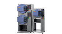
- Dedicated High Temperature Reverse Bias Test System is available for power device evaluation.
- This can measure and evaluate leak current behavior under stress conditions due to high temperature and high voltage in time dependent breakdown tests of insulating film of power devices.
Reverse bias testing can be performed with a maximum testing temperature of 350°C and a maximum testing voltage of 3000V.
Recommended products for customers viewing this product
- Contact us
- Customer Support Desk
Measurement & Evaluation Systems / Semiconductor-related Equipment
-
Measurement & Evaluation Systems
- Electro-chemical Migration Evaluation System(Leakage Current Evaluation System)
- High Voltage Bias Insulation Resistance Evaluation System
- Capacitor Leakage Test System
- High Temperature Reverse Bias Test System
- TDDB (Time-Dependent Dielectric Breakdown) Evaluation System
- Conductor Resistance Evaluation System
- Electromigration Evaluation System
- PV Thermal-Bias Combo Test System
- Semiconductor Parametric Test System
- Capacitor / Inductor Temperature Characteristic Evaluation System
- PV I-V Evaluation System (PV Thermal-Light Combo Test System)
- Power Cycle Test System
- Semiconductor-related Equipment