![]()


- Contact us
-

Environmental testing cannot be performed simply with an environmental test chamber. Various devices must be connected to secure the specimen with the desired conditions and apply and measure electrical stress. Manufacturing a jig that does not have sufficient functions and is unable to obtain satisfactory test results can lead to a loss of time and money. In addition, it can be time consuming to create a jig if you do not have the technical know-how. The keys to evaluation are reliability, durability, and cost. These environmental test jigs provide total support for your testing environment.
- For film-type specimens
-
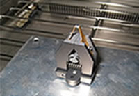
- Probe grip jig (series probe type)
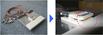
-
- Probe grip jig (independent probe and measurement system linked type)
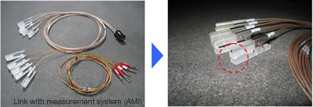
- When evaluating the insulation reliability of electronic parts with a film shape, such as Flexible Printed Circuits (FPC), the connection of the measurement cable to the electrode is very difficult, and in some cases, it may be impossible to ignore the effects on test quality with a connection that cannot use solder material. In this case, the pictured clip type jig is ideal. Not only is it possible to establish a contact to the electrode, but the ease of connection can greatly reduce the operation time.
In addition to being used with film, it can also be used with general print and glass substrates. It supports high temperature and humidity (85°C/85% RH) as well as HAST and other conditions.
- For chip condenser
-
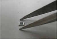
- Contact clip jig (patent pending)
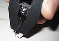
- The tip of the contact clip is a tweezer-style electrode. Hold the contact clip downward to pick up a part.
- Turn right-side up the contact clip holding the part and insert it into the socket of the jig placed in the chamber to complete installation.
-
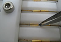
- Conventional type jig for chip condenser
- Use tweezers to pick up the part.
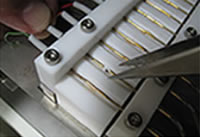
- Place the part pulled with the contact probe and picked up with the tweezers between the electrodes.
- Because chip condensers are recently being made more compact and to resist high voltage, product reliability continues to be important. To test these samples, a jig that can secure the specimen and contact with the electrode has become essential. Here are two jigs, a conventional type and a contact clip type with integrated tweezer function, as jig examples.
- Specifications
-
Jig name Item Specification value - Probe clip type (for film-type specimens)
Usage temperature/humidity range 85°C, 85% RH or 130°C, 85% RH Withstand voltage 1 V to 1000 V Insulation guarantee 1.0×10¹³Ω or more Number of measurements Optional (Can be set according to number required) Price Please inquire - Contact clip type
- Jig for chip condenser (for chip condenser)
Usage temperature/humidity range 85°C, 85%RH or 130°C/85RH Withstand voltage 1 V to 1000 V Insulation guarantee 1.0×10¹³Ω or more Number of measurements Optional (Can be set according to number required) Price Please inquire
Recommended products for customers viewing this product


